There are three RRC states; RRC_IDLE, RRC_INACTIVE, and RRC_CONNECTED are defined for a
5G NR UE. While RRC_IDLE and RRC_CONNECTED states in NR are almost same as
those of LTE, the RRC_INACTIVE states is newly introduced in 5G NR.
After power up, the UE is in idle mode and in order
to perform data transfer or to make/receive voice calls, the UE need to
establish connection with the network which is done using initial access via
RRC connection establishment procedure. Once RRC connection is established, the
UE is in RRC_CONNECTED mode.
In LTE, if there is no activity to/from the UE for a
certain amount of time, the network would order the UE to move to RRC_IDLE
state. This is done to reduce UE’s power consumption. Whenever UE needs to
perform some activity, it needs to transition to the connected mode which
involves in some RRC signalling and hence increased latency. Moreover, today’s
smart phones keep sending small amounts of data very frequently, leading to a regular
Idle-Connected-Idle transitions. These frequent transitions result in increased
network signalling load in addition to increased latency. Therefore, 5G NR has
defined a new state called RRC_INACTIVE to reduce network signalling load as
well as to reduce latency involved in transitioning to RRC_CONNECTED state.
In summary, a UE is in RRC_CONNECTED when an RRC
connection has been established or in RRC_INACTIVE (if the UE is connected to
5GC) when RRC connection is suspended. If this is not the case, i.e. no RRC
connection is established, the UE is in RRC_IDLE state.
Its worth to note that in Non-Standalone (NSA) mode
of operation, only RRC_CONNECTED state is applicable for NR cell.
In this post, all these RRC states are discussed in detail, subsequently
5G NR state transitions are discussed.
RRC_IDLE state
In
RRC_IDLE state, the UE is not registered to a particular cell, hence the UE
doesn’t have an AS context and any other information received from the network.
The network
initiates the RRC connection release procedure to transit a UE in RRC_CONNECTED
to RRC_IDLE state.
The UE is in
(kind of) sleep mode and wakes up periodically (according to a configured DRX
cycle) and monitors for paging messages from the network. The network can reach
UEs in RRC_IDLE state through Paging messages, and to notify UEs in
RRC_IDLE change of system information change and ETWS/CMAS indications through Short
Messages. Both Paging messages and Short Messages are
addressed with P-RNTI on PDCCH, but while the former is sent on PCCH, the
latter is sent over PDCCH. For more details, read RNTIs in 5G NR.
While in
RRC_IDLE, the UE monitors the paging channels for CN-initiated paging; in
RRC_INACTIVE the UE also monitors paging channels for RAN-initiated paging. A
UE need not monitor paging channels continuously though; Paging DRX is defined
where the UE in RRC_IDLE or RRC_INACTIVE is only required to monitor paging
channels during one Paging Occasion (PO) per DRX cycle.
In this state,
the UE itself manages mobility based on the network configurations via cell
(re-) selections. The UE performs the required neighbouring cell measurements
which are required for cell (re-) selections.
On transition
from RRC_CONNECTED or RRC_INACTIVE to RRC_IDLE, a UE should camp on a cell as
result of cell selection according to the frequency be assigned by RRC in the
state transition message if any.
In RRC_IDLE
state, the UE cannot transmit anything in the uplink except for PRACH as part
of RA procedure
initiated when UE desires to transit to RRC_CONNECTED state or to request for On-demand
system information.
A UE in RRC_IDLE,
shall ensure having a valid version of (at least) the MIB, SIB1 through
SIB4 and SIB5 (if the UE supports E-UTRA).
RRC_INACTIVE state
As explained before, RRC_INACTIVE state
is used to reduce network signaling
load as well as to reduce latency involved in transitioning to RRC_CONNECTED
state. Moreover, the UE in RRC_INACTIVE state is allowed to behave similar way
as in RRC_IDLE state to save power.
In RRC_INACTIVE state, the AS context is stored by both UE and gNB, as a
result of which the state transition from inactive state to connected state is faster.
Moreover, the core network connection is also maintained (UE remains in
CM-CONNECTED).
Similar to
RRC_IDLE, the UE is in (kind of) sleep mode and wakes up periodically (according
to configured DRX cycle) and monitors for paging messages from the network. The
network can reach UEs in RRC_INACTIVE state through Paging messages, and
to notify UEs in RRC_INACTIVE, change of system information and ETWS/CMAS
indications through Short Messages. Both Paging messages and Short
Messages are addressed with P-RNTI on PDCCH, but while the former is sent
on PCCH, the latter is sent over PDCCH directly.
-
The UE Monitors a
Paging channel for CN paging using 5G-S-TMSI and RAN paging using fullI-RNTI
(Inactive RNTI). I-RNTI is used to identify the suspended UE context of a UE in
RRC_INACTIVE state. The network assigns I-RNTI to the UE when moving from
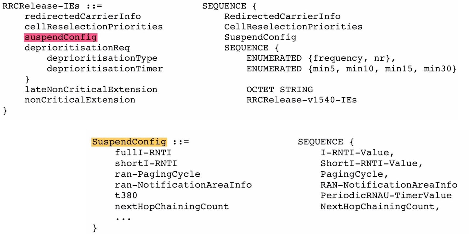
RRC_CONNECTED to RRC_INACTIVE state in RRCRelease message within SuspendConfig.
In RRC_INACTIVE
state, the UE cannot transmit anything in the uplink except for PRACH as part
of RA procedure
initiated when UE desires to transit to RRC_CONNECTED state (to transmit RRCResumeRequest)
or to request for On-demand system information.
The gNB can send a UE from RRC_CONNECTED to RRC_INACTIVE state by
transmitting RRCRelease message with suspendConfig (as shown below).
The field suspendConfig (explained below) provides the UE with the
required configuration for the RRC_INACTIVE state.
-
fullI-RNTI
(40-bits): Inactive-RNTI (I-RNTI) is used to identify the suspended UE context
in RRC_INACTIVE state. A UE in RRC_INACTIVE state can be addressed in paging
message using fullI-RNTI.
-
shortI-RNTI
(24-bits): It is used to identify the suspended UE context of a UE in
RRC_INACTIVE using fewer bits compared to fullI-RNTI.
-
ran-NotificationAreaInfo:
Used for mobility management, network ensures that the UE in RRC_INACTIVE
always has a valid ran-NotificationAreaInfo.
-
ran-PagingCycle:
The UE specific paging cycle for RAN-initiated paging.
-
t380:
Timer that triggers the periodic RNA update procedure in the UE.
Transition from RRC_INACTIVE to RRC_CONNECTED state
The resumption
of a suspended RRC connection is initiated by upper layers when the UE needs to
transit from RRC_INACTIVE state to RRC_CONNECTED state or by RRC layer to
perform an RNA update or by RAN paging from NG-RAN. The RRC connection resume
procedure re-activates AS security and re-establishes SRB(s) and DRB(s).
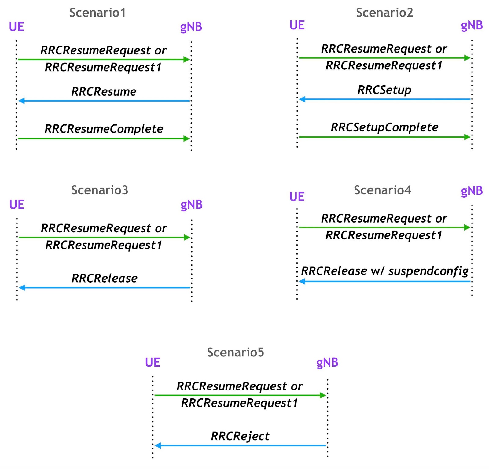
As shown below,
in response to a request to resume the RRC connection, the network may resume
the suspended RRC connection and send UE to RRC_CONNECTED, or reject the
request to resume and send UE to RRC_INACTIVE (with a wait timer), or directly
re-suspend the RRC connection and send UE to RRC_INACTIVE, or directly release
the RRC connection and send UE to RRC_IDLE, or instruct the UE to initiate NAS
level recovery (in this case the network sends an RRC setup message).
-
Scenario1:
Successful RRC connection resumption. Transition from RRC_INACTIVE to
RRC_CONNECTED.
-
Scenario2:
RRC connection resume fallback to RRC connection establishment. Transition from
RRC_INACTIVE to RRC_CONNECTED.
-
Scenario3:
RRC connection resume followed by network releasing RRC connection. Transition
from RRC_INACTIVE to RRC_IDLE.
- Scenario4:
RRC connection resume
followed by network suspend. Transition from RRC_INACTIVE to RRC_INACTIVE.
- Scenario5:
RRC connection resume
followed by network reject. Transition from RRC_INACTIVE to RRC_INACTIVE.
Similar to RRC
Connection establishment procedure, RRC connection resumption procedure
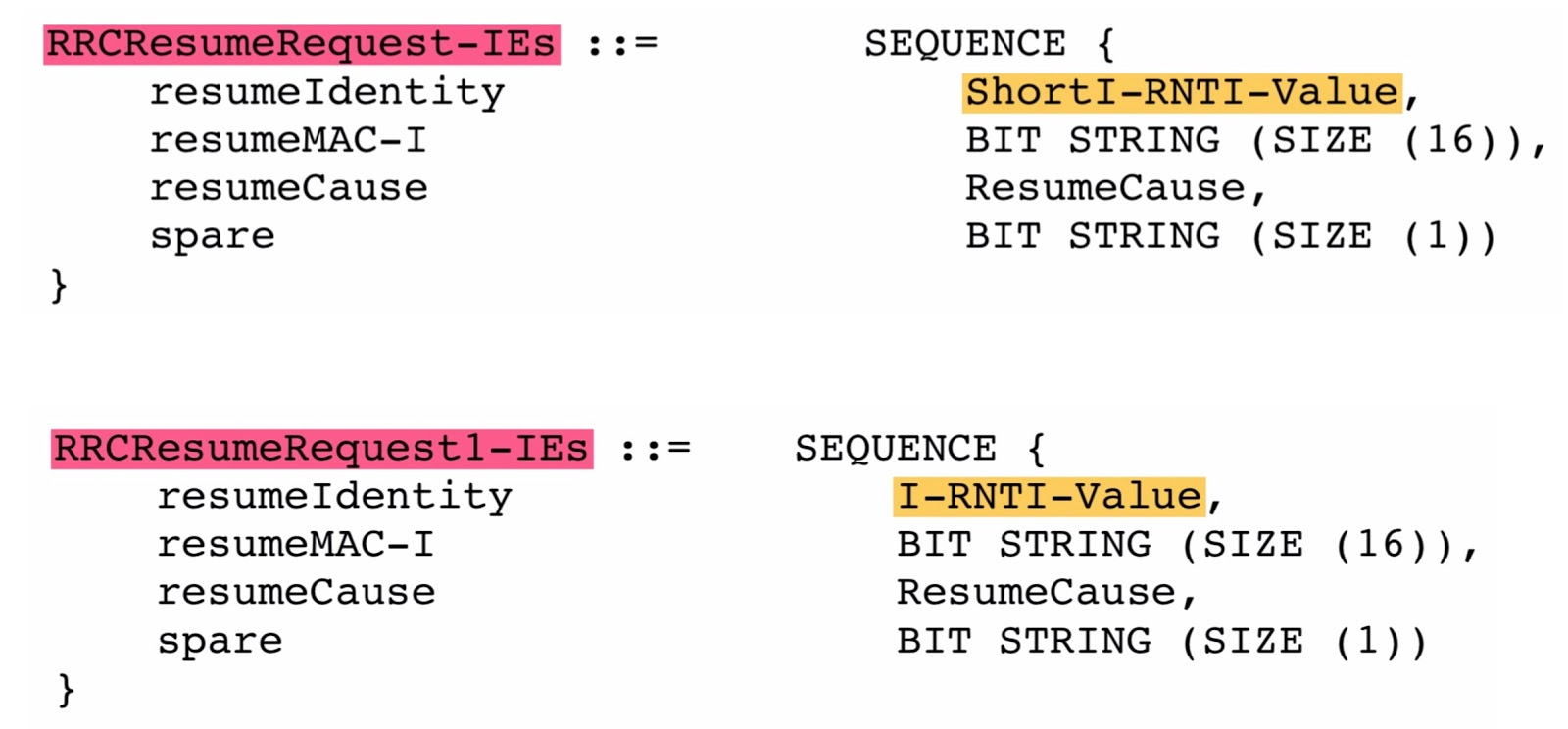
triggers contention basedRA procedure and transmits RRCResumeRequest/RRCResumeRequest1
(UL CCCH) message in MSG3. This message is transmitted in Transparent Mode (TM)
on SRB0. The contents of the resume request message are given below.
Selection between RRCResumeRequest
and RRCResumeRequest1:
-
The network informs the
UE in SIB1 which I-RNTI to be used while resuming the connection (in the RRCResumeRequest
message). If the field useFullResumeID is present in SIB1, the UE shall
use fullI-RNTI, otherwise, the UE shall use shortI-RNTI.
-
While resuming the
connection, if fullI-RNTI to be used, the UE sends RRCResumeRequest1
message and includes fullI-RNTI as resumeIdentity, else if shortI-RNTI
to be used, the UE sends RRCResumeRequest message and includes shortI-RNTI
as resumeIdentity.
ResumeCause
can be one of the following; emergency, highPriorityAccess, mt-Access,
mo-Signalling, mo-Data, mo-VoiceCall, mo-VideoCall, mo-SMS, rna-Update,
mps-PriorityAccess, or mcs-PriorityAccess.
After receiving
resume request from the UE, the network may send RRCResume (DCCH) to
resume suspended RRC Connection. RRCResume is sent on SRB1 using AM
mode. The UE confirms successful completion of an RRC connection resumption
procedure by sending RRCResumeComplete (DCCH) message on SRB1 using AM
mode.
Mobility in RRC_INACTIVE
In RRC_INACTIVE
is a state the UE remains in CM-CONNECTED and can move within an area
configured by NG-RAN (the RNA) without notifying NG-RAN. RNA stands for RAN-based
Notification Area.
In this state,
the last serving gNB node keeps the UE context and the UE-associated NG connection
with the serving AMF and UPF. If the last serving gNB receives downlink data
from the UPF or downlink UE-associated signalling from the AMF, it pages in the
cells corresponding to the RNA and may send XnAP RAN Paging to neighbour gNB(s)
if the RNA includes cells of neighbour gNB(s).
RAN-Based
Notification Area:
A
UE in the RRC_INACTIVE state can be configured (in RRCRelease message
via suspendConfig) by the
last serving NG-RAN node with an RNA, where:
- the
RNA can cover a single or multiple cells, and shall be contained within the CN
registration area.
- a
RAN-based notification area update (RNAU) is periodically sent by the
- RNAU
is also sent when the UE reselects a cell that does not belong to the
configured RNA.
There
are several different alternatives on how the RNA can be configured:
- List
of cells: A UE is provided an explicit list of cells (one or more) that
constitute the RNA.
- List
of RAN areas:
·
A UE is provided (at
least one) RAN area ID, where a RAN area is a subset of a CN Tracking Area or
equal to a CN Tracking Area. A RAN area is specified by one RAN area ID, which
consists of a TAC and optionally a RAN area Code;
·
A cell broadcasts one
or more RAN area IDs in the system information
While transitioning
the UE to RRC_INACTIVE, the NG-RAN node may configure the UE with a periodic
RNA Update timer value (t380). Upon the expiry of this periodic timer,
the UE shall initiate RRC Connection Resume procedure with resumeCause
set to rna-udpate.
A UE in the
RRC_INACTIVE state is required to initiate RNA update procedure (resumeCause
set to rna-Update) when it moves out of the configured RNA i.e., the
serving cell does not belong to the configured ran-NotificationAreaInfo.
When receiving
RNA update request from the UE, the receiving gNB triggers the XnAP Retrieve UE
Context procedure to get the UE context from the last serving gNB and may
decide to send the UE back to RRC_INACTIVE state, move the UE into
RRC_CONNECTED state, or send the UE to RRC_IDLE.
If the UE
accesses a gNB other than the last serving gNB, the receiving gNB triggers the
XnAP Retrieve UE Context procedure to get the UE context from the last serving
gNB.
If the UE
accesses a gNB other than the last serving gNB and the receiving gNB does not
find a valid UE Context, the receiving gNB can perform establishment of a new
RRC connection instead of resumption of the previous RRC connection.
RRC_CONNECTED state
In RRC_CONNECTED
state, an RRC connection is established and the network have configured the UE
with all the required parameters for communication between them.
In this state, the
cell to which the UE belongs to is known and a cell level temporary identity
for the device (C-RNTI) is used to identify the UE in NG-RAN.
In RRC_CONNECTED
state;
-
The UE stores AS
context
-
Transfer of unicast
data to/from UE
-
At lower layers, the UE
may be configured with a UE specific DRX to reduce UE power consumption.
-
For UEs supporting CA,
one or more SCells can be configured to increase aggregated (with SpCell) bandwidth
-
For UEs supporting DC, an
SCG can be configured to increase aggregated (with the MCG) bandwidth;
-
Network controlled
mobility within NR and to/from E-UTRA. The network configures the UE with a set
of neighbour cell measurements, the UE provides the measurement reports to the
network based on which the network may order the UE to perform a handover.
The UE:
-
Monitors Short Messages
transmitted with P-RNTI over DCI, if configured
-
Monitors control
channels associated with the shared data channel to determine if data is
scheduled for it
-
Provides channel
quality and feedback information
-
Performs neighbouring
cell measurements and measurement reporting
-
Acquires system
information
The network can notify
UEs in RRC_CONNECTED state of system information change and ETWS/CMAS
indications through Short Messages. Both Paging messages and Short
Messages are addressed with P-RNTI on PDCCH, but while the former is sent
on PCCH, the latter is sent over PDCCH directly.
UE state machine and state transitions
The following figure
illustrates an overview of UE RRC state machine and state transitions within
NR. A UE has only one RRC state in NR at one time (Reference: 38.331, Figure
4.2.1-1).
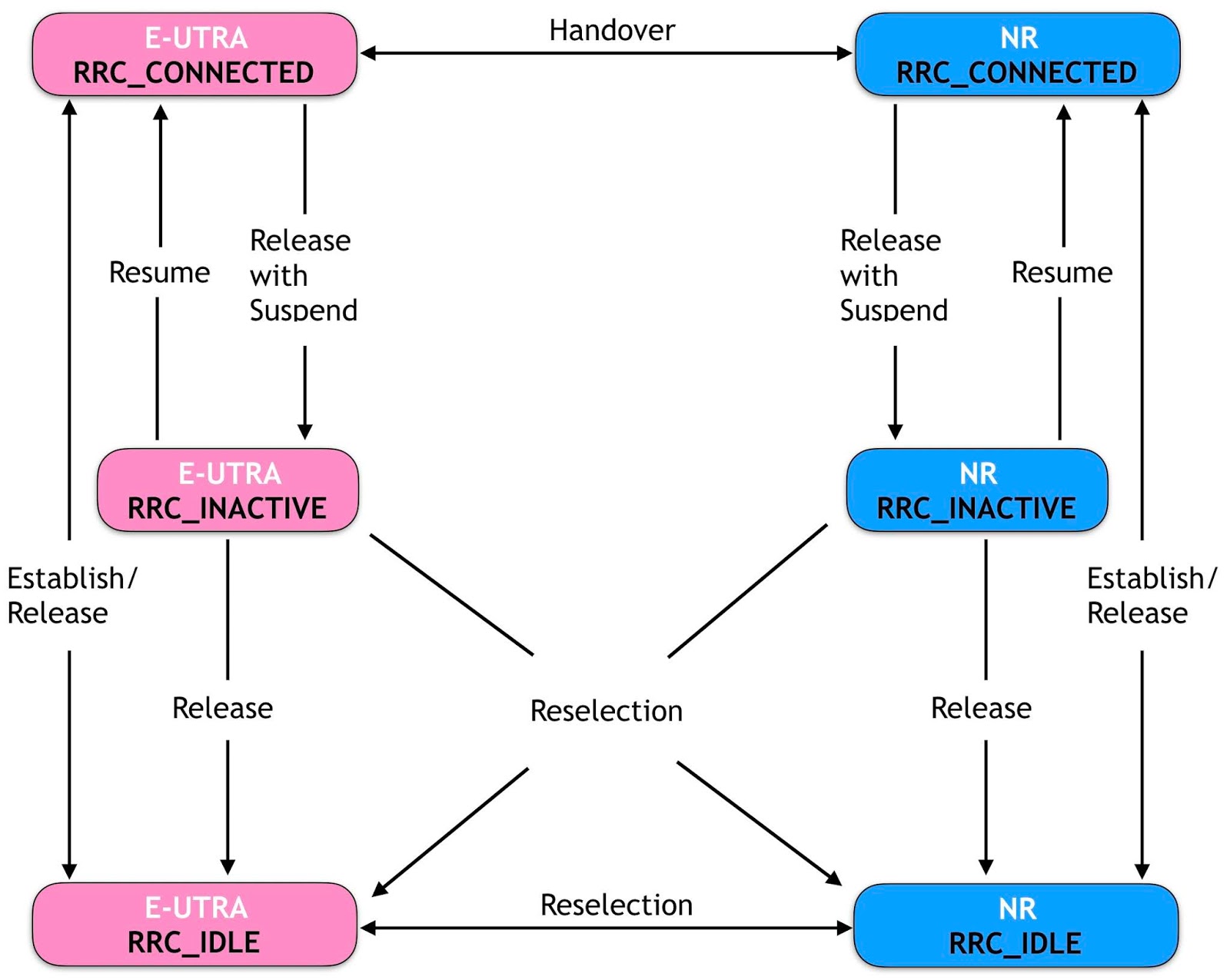
The following
figure illustrates
an overview of UE state machine and state transitions in NR as well as the
mobility procedures supported between NR/5GC, E-UTRA/EPC and E-UTRA/5GC (Reference:
38.331, Figure 4.2.1-2).
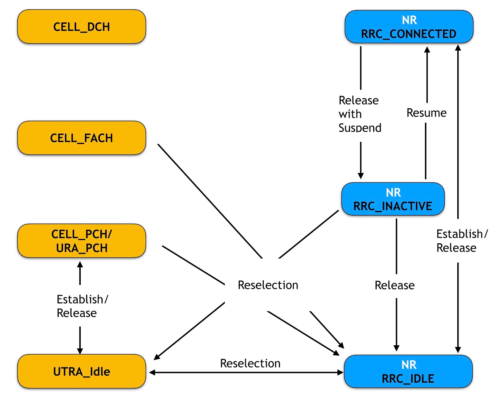
The following figure illustrates UE state machine and state transitions between NR and UTRAN (Reference: 3GPP TR 38.912, Figure 13.2.2-3).
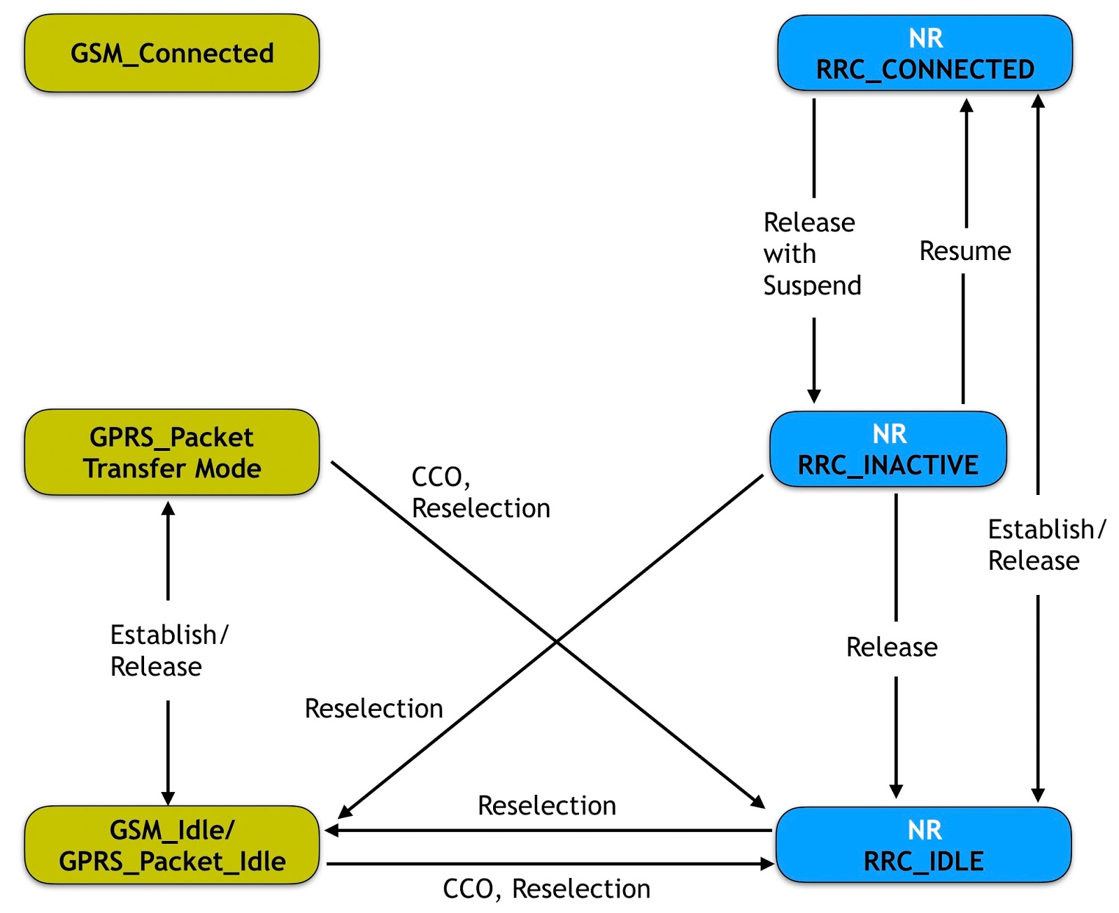
The following figure illustrates UE state machine and state transitions between NR and GERAN (Reference: 3GPP TR 38.912, Figure 13.2.2-3).
Reference: 3GPP TS 38.331, TS 38.300 and TR 38.912
