The
Sounding Reference Signal (SRS) is a reference signal transmitted by the UE in
the uplink direction which is used by the eNodeB to estimate the uplink channel
quality over a wider bandwidth. The eNodeB may use this information for uplink frequency
selective scheduling.
The
eNodeB can also use SRS for uplink timing estimation as part of timing
alignment procedure, particularly in situations like there are no PUSCH/PUCCH
transmissions occurring in the uplink for a long time in which case, the eNodeB
relies on SRS for uplink timing estimation.
SRS
doesn’t need to be transmitted in the same physical resource blocks where PUSCH
is transmitted as SRS may stretch over a larger frequency range.
There
are 3 types of SRS transmissions defined in LTE. From release-8 onwards ‘Single
SRS’ transmission and ‘Periodic SRS’ transmissions are supported. In
release-10, ‘Aperiodic SRS’ transmission is introduced. We will be discussing each of these types in
detail.
SRS Configuration
‘Single
SRS’ and ‘Periodic SRS’ transmissions are called ‘trigger type 0’ SRS
transmissions which are configured by RRC signalling. ‘Aperiodic SRS’
transmission is called as ‘trigger type 1’ SRS transmission which is configured
by RRC but triggered by DCI.
The
eNodeB configures the UE with UE specific SRS configuration as shown below. UE
specific SRS configuration provides the UE with time domain (subframes) as well
as frequency domain resources.
UE
specific SRS configuration for ‘trigger type 0’ (Periodic or Single)
UE
specific SRS configuration for ‘trigger type 1’ (Aperiodic)
In
addition to the UE specific SRS configuration, cell specific SRS configuration
defines the subframes that can contain SRS transmissions as well as the set of
SRS bandwidths available in the cell. In order to prevent SRS transmissions in
the PUCCH regions of the cell, several SRS bandwidth configurations (srs-SubframeConfig)
are defined.
Single and Periodic SRS
transmissions
The
parameter duration in the UE specific
SRS configuration informs the UE whether single or periodic SRS transmission to
be used.
Single
SRS transmission is very simple one. After receiving RRC Connection
Reconfiguration message with UE specific SRS configuration and parameter duration set to FALSE, the UE transmits SRS only once which is called ‘Single’ SRS
transmission.
If
the parameter duration is set to be TRUE, then the UE
transmits Periodic SRS indefinitely until disabled.
srs-ConfigIndex
defines SRS periodicity and an offset. The periodicity ranges from 2 ms to 320
ms.
srs-Bandwidth
parameter defines the bandwidth that needs to be used while transmitting SRS in
a subframe.
srs-HoppingBandwidth
is defined for the purpose of frequency hopping of SRS. If frequency hopping of
the SRS is enabled, then srs-HoppingBandwidth
is smaller than srs-Bandwidth. SRS
hopping procedure will also be discussed in detail.
freqDomainPosition
defines the starting position of the SRS
in the frequency domain
cyclicShift
can vary from 1 to 8 which generates up to 8 different SRSs which are orthogonal
to each other. The eNodeB can configure SRS for up to 8 UEs in the same
subframe and frequency resources but to use different cyclic shift. The cyclic
shift multiplexed signals need to have the same bandwidth to maintain the
orthogonally.
transmissionComb:
Actually, SRS is transmitted in every alternate (every even or every odd)
subcarrier in the assigned SRS bandwidth. transmissionComb
takes values 0 or 1 which informs whether to transmit SRS in every even or odd
subcarrier in the assigned SRS bandwidth. By doing this the eNodeB can multiplex
two UEs with same cyclicShift, frequency and time resources but different transmissionComb
(0 or 1).
Aperiodic SRS transmissions
Aperiodic
SRS transmissions are defined from Release-10 onwards. Aperiodic SRS
transmission, as the name implies, is single shot SRS transmission based a
trigger.
Aperiodic
SRS is configured by RRC but triggered by ‘SRS request’ flag in PDCCH DCI Formats 0/4/1A (for FDD and TDD) and
DCI Formats 2B/2C for TDD alone.
Before
triggering Aperiodic SRS using DCI Format 0, a single set of parameters srs-ConfigApDCI-Format0 need to be
configured by RRC. Similarly, Aperiodic SRS using DCI formats 1A/2B/2C, a
single common set of parameters srs-ConfigApDCI-Format1a2b2c
should be configured by RRC.
For
triggering Aperiodic SRS using DCI Format 4, three sets of SRS parameters, srs-ConfigApDCI-Format4,
are to be configured by RRC.
For
‘Aperiodic SRS’ trigger using DCI Formats
0/1A/2B/2C, 1-bit ‘SRS request’ field is used whereas DCI Format 4 carries 2-bit ‘SRS request’ field to indicate which of
the three configured parameters set to be used.
The
frequency domain behavior of Aperiodic SRS is same as Periodic SRS.
A
UE configured for Aperiodic SRS transmission upon detection of a positive SRS
request in subframe #n shall commence
SRS transmission in the first subframe satisfying subframe #n+k, k ≥ 4 and based on the Aperiodic SRS time domain
configuration.
SRS transmission in detail
The
SRS configurations for different types of SRS transmissions are already
discussed. We will now look at the contents of SRS, its mapping to physical resources
both in time and frequency.
SRS
uses same sequence as uplink Demodulation Reference Signals (DMRS). Since the
cyclic shift versions of the Zadoff-Chu
sequence are orthogonal, several UEs (up to 8) can transmit using different
cyclic shifts on the same physical radio resource.
In
the configured SRS bandwidth, the SRS will be mapped every alternate subcarrier
(comb-like pattern), on the other hand, since the srs-Bandwidth is always multiple of 4 RBs, SRS sequences are always
a multiple of 24 RBs.
SRS
is always transmitted in the last OFDM symbol in a subframe which is based on srs-ConfigIndex.
Frequency
domain resource selection for SRS transmission
There
are two types of SRS, wide band SRS and narrow band SRS.
Wide
band SRS doesn’t necessarily over the entire system bandwidth but on the entire
bandwidth of interest, whereas narrow band SRS allows the UE to do frequency
hopping between transmissions.
Wide
band SRS is more beneficial from the resource utilization point of view, as the
UE can sound in the entire bandwidth of interest using single SRS transmission.
However, the UE at the cell edge may not have sufficient power to sound over a
wide bandwidth in which case, the eNodeB might configure the UE to use
frequency hopping for SRS.
In
the frequency domain, SRS is transmitted in srs-Bandwidth
which is multiple of 4RBs. Tables 5.5.3.2-1 to 5.5.3.2-4 in 36.311 defines 4 srs-Bandwidths based on 1 of 8 srs-BandwidthConfigs which is Cell
specific bandwidth configuration. One such table is shown below.
Let
us consider the following example in FDD to understand how SRS is spread in the
frequency domain in terms of PRBs. Let the System Bandwidth = 10MHz (50 PRBs), srs-BandwidthConfig (From SIB2) = bw0, freqDomainPosition
= 0, transmissionComb = 1.
Since
the system Bandwidth is 50 PRBs, there are a total of 600 subcarriers (0…599)
Example 1:
Wide band SRS (no SRS Hopping)
Consider srs-Bandwidth
= bw0 and srs-HoppingBandwidth =
hbw0.
Since
srs-Bandwidth is equal to srs-HoppingBandwidth, frequency hopping
is not enabled. From the Table 5.5.3.2-2 (presented above), srs-Bandwidth of bw0 corresponds to 48 PRBs.
In
the subframe where SRS is transmitted, starting from subcarrier number 13,
every alternate subcarrier (13, 15, 17… 585, 587) is used for SRS transmission.
The
eNodeB can allocate same time and RBs for another UE by setting transmissionComb = 0 (all other
parameters are same). This implies that second UE sends SRS on subcarriers (12,
14, 16… 584, 586).
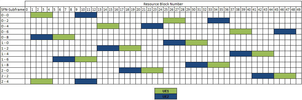
Example 2:
SRS Frequency Hopping
If
frequency hopping of the SRS is enabled, then srs-HoppingBandwidth is smaller than srs-Bandwidth. Let us consider srs-Bandwidth
= bw3 and srs-HoppingBandwidth = hbw0 ⇨
SRS bandwidth = 4 PRBs and SRS Hopping Bandwidth = 48 PRBs.
Consider
two UEs, UE1 and UE2. Let transmissionComb
= 0 for both of the UEs and freqDomainPosition
= 0 for UE1 and freqDomainPosition =
2 for UE2.
Since
srs-Bandwidth is set to 3, both of
the UEs use 4 RBs in every subframe for SRS transmission. It can be seen that
UE1 is transmitting SRS over the entire bandwidth of interest (SRS Hopping
Bandwidth = 48 PRBs) but not in single shot. Similar behavior holds good for
UE2 as well.
There can be a lot of combinations considered. In a single subframe, the
eNodeB can configure all 48 PRBs to UE1 with transmissionComb = 0, and
configure a couple of UEs with 4 PRBs but using transmissionComb = 1. Similarly,
other combinations of various SRS bandwidths of 4, 12, 24, and 48 resource
blocks can be considered
One
can try several combinations using different parameters for calculating SRS
resources (frequency domain starting position) using the tool given at the end
of this post.
Time
domain resource selection for SRS transmission
In
the time domain, a resource is nothing but the subframe where SRS transmission
has to happen.
Based
on srs-SubframeConfig in SIB2, the UE
first derives cell specific SRS subframe. These subframe (s) are common to all
the UEs in the cell.
Different
UEs are configured with different UE specific SRS configuration, based on which
each UE derives UE specific SRS subframe.
The
UE transmits SRS only if the ‘UE specific SRS subframe’ coincides with ‘Cell
specific SRS subframe’.
Example:
Let us consider srs-SubframeConfig = sc8
and srs-ConfigIndex = 0.
From
Table 5.5.3.3-1 in 36.211, subframes 2, 3, 7, and 8 are cell-specific
subframes. From srs-ConfigIndex, UE
specific subframes are 0, 2, 4, 6, and 8. So the UE transmits SRS in subframes
2 and 8.
When
SRS is being transmitted by a UE in a subframe, it may overlap in frequency
with PUSCH being transmitted by another UE. Due to this reason, none of the UEs
in the cell transmits PUSCH in the last OFDM symbol of a cell specific SRS subframe. Since all UEs are aware of cell specific SRS
configuration, they can take care of not transmitting PUSCH in the last OFDM
symbol of the cell specific SRS subframe.
A
UE does not transmit SRS whenever SRS and CQI transmissions happen to coincide
in the same subframe.
A
UE shall not transmit SRS whenever SRS transmission and PUCCH transmission
carrying HARQ-ACK and/or Scheduling Request happen to coincide in the same
subframe if the parameter ackNackSRS-SimultaneousTransmission in SIB2 is set to
FALSE.
A
UE shall transmit SRS whenever SRS transmission and PUCCH transmission carrying
HARQ-ACK and/or Scheduling Request using shortened PUCCH format happens to
coincide in the same subframe if the parameter ackNackSRS-SimultaneousTransmission
is TRUE. In this case, the UE shall transmit shortened PUCCH format where the
HARQ-ACK or the SR symbol corresponding to the SRS location is punctured.
The
UE shall use shortened PUCCH format in a cell specific SRS subframe even
if the UE does not transmit SRS in that subframe.
In
case both periodic and aperiodic SRS transmissions would occur in the same
subframe in the same serving cell, the UE shall only transmit the Aperiodic
SRS.
A
UE shall not transmit SRS whenever SRS and a PUSCH transmission corresponding
to a RAR Grant or a retransmission of the same TB as part of the contention
based RA procedure coincide in the same subframe.
SRS
transmission in TDD
In
TDD, SRS can be transmitted in uplink as well as in special subframes (UpPTS).
Based
on the special subframe configuration (Table 4.2-1 from 36.211), the UpPTS
length varies (one or two OFDM symbols).
When
one SC-FDMA symbol exists in UpPTS, it can be used for SRS transmission.
When
two SC-FDMA symbols exist in UpPTS, both can be used for SRS transmission and
both can be assigned to the same UE.
In
UpPTS, whenever SRS transmission instance overlaps with the PRACH region for
preamble format 4, the UE shall not transmit SRS
The
following ‘SRS Calculator’ can be used to calculate SRS transmission resources
(in time as well as frequency domain) for FDD. TDD support will be added very
soon.
Reference:
3GPP TS 36.211, 36.213, and 36.331
SRS calculations