LTE: UL Information Transfer

Direction: UE => E-UTRAN
Signalling Radio Bearer: SRB1 or SRB2
RLC Mode: AM
Logical Channel: DCCH
Transport Channel: UL-SCH

A UE in RRC_CONNECTED state initiates the UL INFORMATION TRANSFER whenever there is a need to transfer NAS or non-3GPP dedicated information, except at RRC connection establishment in which case the NAS information is piggybacked to the RRC CONNECTION SETUP COMPLETE message

The UL INFORMATION TRANSFER procedure is almost similar to UPLINK DIRECT TRANSFER procedure in 3G-RNC

Either SRB2 or SRB1 (only if SRB2 not established yet) is used for this purpose. If SRB2 is suspended, the UE does not send this message until SRB2 is resumed. When CDMA2000 information has to be transferred, the UE shall initiate the procedure only if SRB2 is established

The IE dedicatedInfoType shall carry ‘dedicatedInfoNAS’ or ‘dedicatedInfoCDMA2000-1XRTT ‘(in case of CDMA2000 1XRTT information) or ‘dedicatedInfoCDMA2000-HRPD’ (in case of CDMA2000 HRPD information)

Example1: UL INFORMATION TRANSFER message (carrying Authentication Response)

Example2: UL INFORMATION TRANSFER message (carrying Authentication Failure)


Reference: 3GPP TS 36.331

LTE: Measurement Report

Direction: UE => E-UTRAN
Signalling Radio Bearer: SRB1
RLC Mode: AM
Logical Channel: DCCH
Transport Channel: UL-SCH

The UE reports measurement information in accordance with the measurement configuration as provided by E-UTRAN. E-UTRAN provides the measurement configuration applicable for a UE in RRC_CONNECTED by means of dedicated signalling, i.e. using the RRC CONNECTION RECONFIGURATION message

The UE can be requested to perform the following types of measurements:
  • Intra-frequency measurements: Measurements at the downlink carrier frequency (ies) of the serving cell(s).
  • Inter-frequency measurements: Measurements at frequencies that differ from any of the downlink carrier frequency (ies) of the serving cell(s).
  • Inter-RAT measurements of UTRA frequencies or of GERAN frequencies or of CDMA2000 HRPD or CDMA2000 1xRTT frequencies

Example: MEASUREMENT REPORT message – Intra E-UTRAN measurements


Example: MEASUREMENT REPORT message – InterRAT measurements


Reference: 3GPP TS 36.331

LTE: Mobility from E-UTRA Command

E-UTRAN initiates the 'mobility from E-UTRA' procedure to a UE in RRC_CONNECTED state. The eNodeB sends MOBILITY FROM EUTRA COMMAND possibly in response to a 'Measurement Report' message from the UE or in response to reception of 'CS fallback indication' for the UE from MME. This procedure is initiated only when AS-security has been activated.

The purpose of this procedure is to move a UE from E-UTRAN to a cell using another RAT, e.g. GERAN, UTRA or CDMA2000 systems. The mobility from E-UTRA procedure covers the following types of mobility:
1.      Handover, i.e. the MOBILITY FROM EUTRA COMMAND message includes radio resources that have been allocated for the UE in the target cell
2.      Cell Change Order, i.e. the MOBILITY FROM EUTRA COMMAND message may include information facilitating access of and/or connection establishment in the target cell, e.g. system information. Cell change order is applicable only to GERAN
3.      Enhanced CS fallback to CDMA2000 1xRTT, i.e. the MOBILITY FROM EUTRA COMMAND message includes radio resources that have been allocated for the UE in the target cell

MOBILITY FROM EUTRA COMMAND message

Direction: E-UTRAN => UE
Signalling Radio Bearer: SRB1
RLC Mode: AM
Logical Channel: DCCH
Transport Channel: DL-SCH

Some of the IEs in MOBILITY FROM EUTRA COMMAND message are described below: 

cs-FallbackIndicator: Indicates if the CS Fallback procedure to UTRAN or GERAN is triggered
Purpose: Indicates which type of mobility procedure the UE is requested to perform (Handover, CCO, eCSFB etc…)
TargetRAT-Type: This IE indicates the target RAT type (utra, geran, cdma2000-1XRTT, cdma2000-HRPD)
TargetRAT-MessageContainer: This field contains a message specified in another standard, as indicated by the targetRAT-Type. It carries information about the target cell identifier(s) and radio parameters relevant for the target RAT. This means that the actual handover command message is built by the target RAT and is sent to the source eNodeB. The source eNodB includes this actual handover command in the MOBILITY FROM EUTRA COMMAND
CarrierFreq: Contains the carrier frequency of the target GERAN cell
SystemInfoListGERAN: If the IE ‘purpose’ is CCO and if this field is not present, the UE has to acquire SI/PSI from the GERAN cell

Example: MOBILITY FROM EUTRA COMMAND  message


Mobility from E-UTRA failure
Either of the following condition is treated as ‘Mobility from E-UTRA failure
·           T304 expiry (mobility from E-UTRA failure)
·            If the UE does not succeed in establishing the connection to the target RAT
·            If the UE is unable to comply with (part of) the configuration included in the MobilityFromEUTRACommand message
·            If there is a protocol error in the inter RAT information included in the MobilityFromEUTRACommand message, causing the UE to fail the procedure according to the specifications applicable for the target RAT

If the criteria for ‘Mobility from E-UTRA failure’ is met,then the UE should stop T304, if running and act as below:
·            If the cs-FallbackIndicator in the MobilityFromEUTRACommand message was set to 'TRUE', indicate to upper layers that the CS Fallback procedure has failed
·            Revert back to the configuration used in the source cell, excluding the configuration configured by the physicalConfigDedicated, mac-MainConfig and sps-Config
·            Initiate the connection re-establishment procedure
Reference: 3GPP TS 36.331

LTE: RRC Connection Reestablishment Reject

Direction: E-UTRAN => UE
Signalling Radio Bearer: SRB0
RLC Mode: TM
Logical Channel: CCCH
Transport Channel: DL-SCH

The RRC CONNECTION REESTABLISHMENT REJECT message is used to indicate the rejection of an RRC CONNECTION REESTABLISHMENT REQUEST.

Upon receiving the RRC CONNECTION REESTABLISHMENT REJECT message, the UE shall leave RRC_CONNECTED state with release cause 'RRC connection failure'

Example: RRC CONNECTION REESTABLISHMENT REJECT message


Reference: 3GPP TS 36.331

LTE: RRC Connection Reestablishment Complete

Direction: UE => E-UTRAN
Signalling Radio Bearer: SRB1
RLC Mode: AM
Logical Channel: DCCH
Transport Channel: UL-SCH

The RRC CONNECTION REESTABLISHMENT COMPLETE message is used to confirm the successful completion of an RRC connection reestablishment

After receiving RRC CONNECTION REESTABLISHMENT message, the SRB1 operation is resumed. The RRC CONNECTION REESTABLISHMENT COMPLETE message and all the subsequent messages are (sent) ciphered and integrity protected using previously configured (respective) algorithms and newly derived keys KRRCenc and KRRCint respectively.

Example: RRC CONNECTION REESTABLISHMENT COMPLETE message


Reference: 3GPP TS 36.331

LTE: RRC Connection Reestablishment

Direction: E-UTRAN => UE
Signalling Radio Bearer: SRB0
RLC Mode: TM
Logical Channel: CCCH
Transport Channel: DL-SCH

The purpose of this procedure is to re-establish the RRC connection, which involves the resumption of SRB1, the re-activation of security and the configuration of only the PCell

The RRC CONNECTION REESTABLISHMENT message is used to resolve contention and to re-establish SRB1. Since this message is used to resume SRB1, it is similar to RRCCONNECTION SETUP

See RRC CONNECTION REESTABLISHMENT REQUEST for more information on RRC Reestablishment procedure

Reference: 3GPP TS 36.331

Example: RRC CONNECTION REESTABLISHMENT

LTE: RRC Connection Reestablishment Request

The purpose of RRC CONNECTION RE-ESTABLISHMENT procedure is to re-establish the RRC connection, which involves the resumption of SRB1 operation and the re-activation of security (without changing algorithms). The UE shall only initiate this procedure when AS security has been activated.

 The connection re-establishment succeeds only if the concerned cell is prepared i.e. has a valid UE context. In case E-UTRAN accepts the re-establishment, SRB1 operation resumes while the operation of other radio bearers remains suspended. If AS security has not been activated, the UE doesn’t initiate this procedure, instead, it moves to RRC_IDLE directly

The UE initiates the RRC CONNECTION RE-ESTABLISHMENT procedure when one of the following conditions is met:
  • Upon detecting radio link failure; or
  • Upon handover failure; or
  • Upon mobility from E-UTRA failure; or
  • Upon integrity check failure indication from lower layers; or
  • Upon an RRC CONNECTION RECONFIGURATION failure

RRC Connection Reestablishment Request Message

Direction: UE => E-UTRAN
Signalling Radio Bearer: SRB0
RLC Mode: TM
Logical Channel: CCCH
Transport Channel: UL-SCH

IEs in RRC CONNECTION REESTABLISHMENT REQUEST message are given below:

ue-Identity: UE identity is included to retrieve UE context and to facilitate contention resolution by lower layers. The UE Identity shall be set as follows:
  1. Set the C-RNTI to the C-RNTI used in the source PCell (In case of handover and mobility from E-UTRA failure) or used in the PCell in which the trigger for the re-establishment occurred (other cases);
  2. Set the physCellId to the physical cell identity of the source PCell (handover and mobility from E-UTRA failure) or of the PCell in which the trigger for the re-establishment occurred (other cases);
  3. Set the shortMAC-I to the 16 least significant bits of the calculated MAC-I
 reestablishmentCause: This IE indicates the failure cause that triggered the re-establishment procedure and shall be set as follows:
  1. If the re-establishment procedure was initiated due to reconfiguration failure (the UE is unable to comply with the reconfiguration sent in RRC CONNECTION RECONFIGURATION), then set the reestablishmentCause to the value 'reconfigurationFailure';
  2. If the re-establishment procedure was initiated due to handover failure (intra-LTE handover failure or inter-RAT mobility from EUTRA failure) then, set the reestablishmentCause to the value 'handoverFailure'
  3. Set the reestablishmentCause to the value 'otherFailure' if the re-establishment procedure was triggered due other causes than indicated in cases 1 and 2
Example: RRC CONNECTION REESTABLISHMENT REQUEST


Reference: 3GPP TS 36.331

LTE: RRC Connection Reconfiguration Complete

Direction: UE => E-UTRAN
Signalling Radio Bearer: SRB1
RLC Mode: AM
Logical Channel: DCCH
Transport Channel: UL-SCH


The RRC CONNECTION RECONFIGURATION COMPLETE message is used to confirm the successful completion of an RRC CONNECTION RECONFIGURATION

Example: RRC CONNECTION RECONFIGURATION COMPLETE
Reference: 3GPP TS 36.331

LTE: RRC Connection Reconfiguration

Direction: E-UTRAN => UE
Signalling Radio Bearer: SRB1
RLC Mode: AM
Logical Channel: DCCH
Transport Channel: DL-SCH


RRC CONNECTION RECONFIGURATION message is the command to modify an RRC connection. The purpose of this procedure is,
·            To establish/modify/release Radio Bearers
·            To perform Handover
·            To setup/modify/release Measurements
·            To add/modify/release SCells
·            Dedicated NAS Information might also be transferred from eNodeB to UE

Differences with 3G system's radio resource configuration procedure:
·         In LTE, RRC CONNECTION RECONFIGURATION is the only message used to perform all logical, transport, and physical channel configurations where as in case UMTS, there exists Transport Channel, Physical Channel and Radio Bearer Reconfiguration messages
·         In LTE, RRC CONNECTION RECONFIGURATION can also be used to send NASdedicated signalling to the UE to reduce the latency whereas this option is not available in 3G
·         LTE has only one RRC connected mode state (RRC_CONNECTED), so it has only one Temporary Radio Network Temporary Identity (RNTI) i.e. C-RNTI
·         In 3G, MEASUREMENT CONTROL is used to setup/modify/release measurements where as in LTE, RRC CONNECTION RECONFIGURATION message is the only message for this purpose

E-UTRAN includes the mobilityControlInfo (Handover) only when AS-security has been activated, and SRB2 with at least one DRB are setup but not suspended. The establishment of RBs (other than SRB1, which is established during RRC connection establishment) is included only when AS-security has been activated

          If the UE is unable to comply with (part of) the configuration included in the RRC CONNECTION RECONFIGURATION message, the UE shall continue using the configuration used prior to the reception of RRC CONNECTION RECONFIGURATION message. If the security has not been activated, UE should leave RRC_CONNECTED state, else, UE initiates the connection re-establishment procedure which is used to resume SRB1 operation and to reactivate security


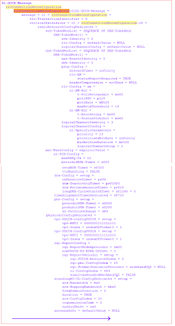
Example1: RRC CONNECTION RECONFIGURATION to setup SRB2 and DRB


Example2: RRC CONNECTION RECONFIGURATION - Measurement Configuration


Example3: RRC CONNECTION RECONFIGURATION - Mobility Config Information


Example4: RRC CONNECTION RECONFIGURATION - DedicatedInfoNAS (Other IEs are not shown)


LTE: UE Capability Information

Direction: UE => E-UTRAN
Signalling Radio Bearer: SRB1
RLC Mode: AM
Logical Channel: DCCH
Transport Channel: UL-SCH

The UE CAPABILITY INFORMATION message is used to transfer of UE radio access capabilities requested by the E-UTRAN in UE CAPABILITY ENQUIRY.

ueCapabilityRAT-Container is the container for the UE capabilities of the indicated RAT. The encoding is defined in the specification of each RAT. For E-UTRA, the encoding of UE capabilities is defined in the IE UE-EUTRA-Capability which is explained below


Some important parameters in UE-EUTRA-Capability IE are given below:
accessStratumRelease: Set to Rel8, Rel9, Rel10 and so on (based on the UE’s  release)
maxNumberROHC-ContextSessions: Set to the maximum number of concurrently active ROHC contexts supported by the UE. cs2 corresponds with 2 (context sessions), cs4 corresponds with 4 and so on
ue-Category:  As per Rel10, the possible values are 1 to 8 (Ref: TS 36.306)
ue-TxAntennaSelectionSupported: TRUE indicates that the UE is capable of supporting UE transmit antenna selection as described in TS 36.213
halfDuplex: If halfDuplex is set to true, only half duplex operation is supported for the band, otherwise full duplex operation is supported. This entry is present in each of the supported bands
bandListEUTRA: One entry corresponding to each supported E-UTRA band listed in the same order as in supportedBandListEUTRA
interFreqBandList: One entry corresponding to each supported E-UTRA band listed in the same order as in supportedBandListEUTRA
interFreqNeedForGaps: Indicates need for measurement gaps when operating on the E-UTRA band given by the entry in bandListEUTRA and measuring on the E-UTRA band given by the entry in interFreqBandList
interRAT-BandList: One entry corresponding to each supported band of another RAT listed in the same order as in the interRAT-Parameters
interRAT-NeedForGaps: Indicates need for DL measurement gaps when operating on the E-UTRA band given by the entry in bandListEUTRA and measuring on the inter-RAT band given by the entry in the interRAT-BandList
SupportedBandUTRA-FDD: UTRA band as defined in TS 25.101
SupportedBandGERAN: GERAN band as defined in TS 45.005

featureGroupIndicators, featureGroupIndRel9Add, featureGroupIndRel10: These featureGroupIndicators IE is a bit string, where each bit indicate support for a specific feature. The definitions of the bits in the bit string are described in Annex B.1 (for featureGroupIndicators and featureGroupIndRel9Add) and in Annex C.1.(for featureGroupIndRel10) of 36.331


Example: UE CAPABILITY INFORMATION


Reference: 3GPP TS 36.331

LTE: UE Capability Enquiry

Direction: E-UTRAN => UE
Signalling Radio Bearer: SRB1
RLC Mode: AM
Logical Channel: DCCH
Transport Channel: DL-SCH

The UE CAPABILITY ENQUIRY message is used to request the transfer of UE radio access capabilities for E-UTRA as well as for other RATs (UTRA, GERAN-CS, GERAN-PS, and CDMA2000)

As the UE’s AS capability may contain several RATs capabilities, the information can be rather very large. To reduce the overhead in the air interface during transition from RRC_IDLE mode to RRC_CONNECTED mode, MME stores UE's AS capability and provides it to eNodeB during initial UE context setup over S1 interface. In case if the MME doesn’t have the valid UE's AS capability, the MME does not provide UE's AS capability to the eNodeB. The eNobeB has to acquire UE's AS capability from UE using UE CAPABILITY ENQUIRY.
NOTE: Change of the UE's GERAN UE radio capabilities in RRC_IDLE is supported by use of TRACKING AREA UPDATE

This message contains only one IE as shown below;
ue-CapabilityRequest: List of the RATs for which the UE is requested to transfer the UE radio access capabilities i.e. E-UTRA, UTRA, GERAN-CS, GERAN-PS, CDMA2000

Example: UE CAPABILITY ENQUIRY for E-UTRA


Reference: 3GPP TS 36.331

LTE RRC: Security Mode Failure

Direction: UE => E-UTRAN
Signalling Radio Bearer: SRB1
RLC Mode: AM
Logical Channel: DCCH
Transport Channel: UL-SCH

The SECURITY MODE FAILURE message is used to indicate an unsuccessful completion of a SECURITY MODE COMMAND. i.e., if the SECURITY MODE COMMAND message fails the integrity protection check, then the UE sends SECURITY MODE FAILURE to the eNodeB

Upon sending this message, the UE shall continue using the configuration used prior to the reception of the SECURITY MODE COMMAND message, i.e. neither applies integrity protection nor ciphering

More details about the security architecture and different kinds of keys are explained here

Reference: 3GPP TS 36.331

LTE RRC: Security Mode Complete

Direction: UE => E-UTRAN
Signalling Radio Bearer: SRB1
RLC Mode: AM
Logical Channel: DCCH
Transport Channel: UL-SCH

The SECURITY MODE COMPLETE message is used to confirm the successful completion of a SECURITY MODE COMMAND.

The UE shall send SECURITY MODE COMPLETE message integrity protected but un-ciphered.
 i.e., the UE doesn’t start ciphering in the uplink before it has sent the SECURITY MODE COMPLETE message to the eNodeB

Example: SECURITY MODE COMPLETE


Reference: 3GPP TS 36.331